¶ RFD868+ Telemetrie Modem
The RFD868+ telemetry modem provides a bidirectional 64 kBit/s link via 868 MHz radio transmission.
¶ Links
- Anleitung PixRacer Autopilot (Pinout TELEM1)
- Taoglas 5dBi 868 MHz Antenne
- Datenblatt RFD868x Modem (neueres Modem mit 32 Bit Prozessor) enthält mechanische Skizze des Modems
- Datenblatt RFD868x Modem - mit Parameterbeschreiebung
- Datenblatt RFD868+ Modem
- FAQs with troubleshooting
¶ Datenkabel Pinbelegung
See Cable connection for the RFD868 modem
¶ Telemetrie Check
Beim Flug am 27.4.2018 ist die Telemetrie ausgefallen. Um die Telemetrie zu testen, kann man die Modems als UART Bridge ohne die PX4 Firmware ausprobieren.
- Zunächst muss man das Telemetrie korrekt anschließen. Dazu braucht man einen Jumper und ein USB Kabel. Der Jumper verbindet Pins 4 und 6. Das USB Kabel muss mit dem Ground auf Pin 1 angeschlossen werden (schwarz), danach auf Pins 3, 5, 7, 9 und 11. Dazu ein Foto:
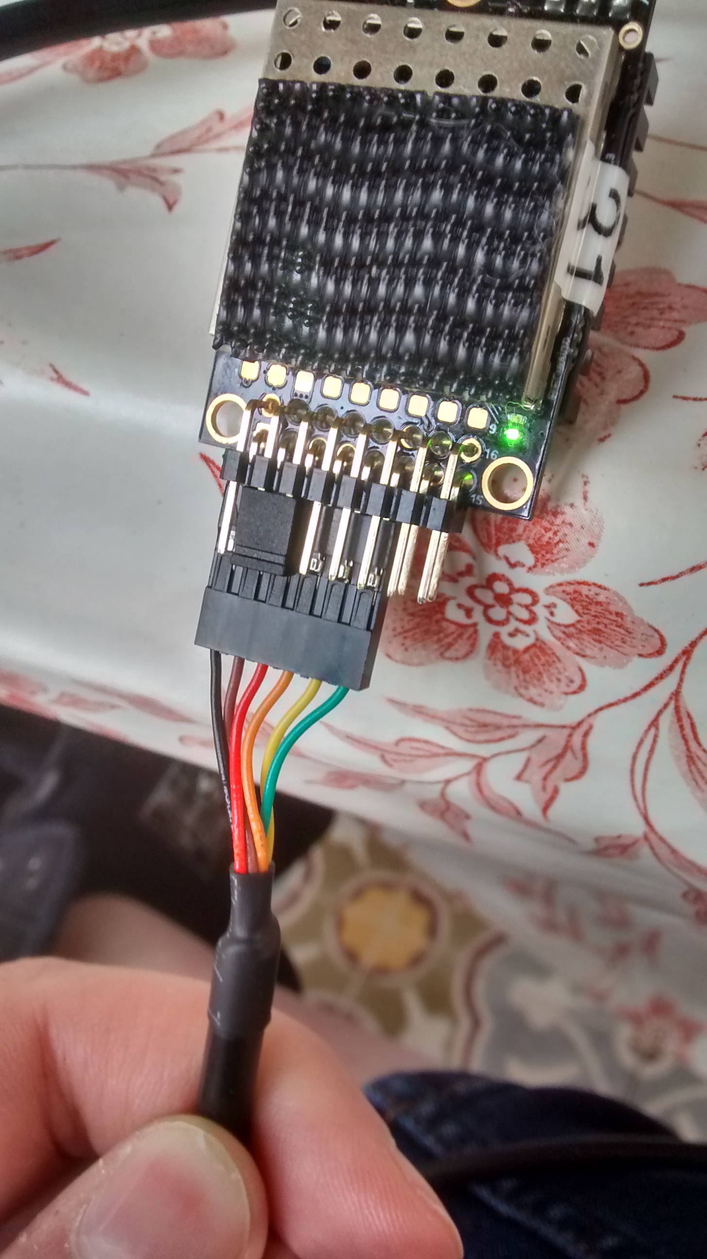
Foto - Unter Linux oder MacOS kann man "screen" als terminal verwenden
- Nach dem Einstecken des Modems erscheint unter /dev/ttyXXXXXXX ein neues Device. Unter Linux ist dies /dev/ttyUSB0, unter MacOS ist dies /dev/tty.usbserial-DM000IKG
- Unter Linux muss man das terminal als root starten und die Baudrate von 57600 Baud angeben.
<!-- -->
sudo screen /dev/ttyUSB0 57600
- Unter MacOS ist kein sudo notwendig
- Dann öffnet sich das Terminal und man muss "+++" eingeben um in den ATI Modus zu kommen. Es erscheint "OK".
- Dann kann man die AT Kommandos benutzen um Informationen über die Linkqualität angezeigt zu bekommen.
- Man muss dazu zwei Modems gleichzeitig angeschaltet haben…
- ATI7 zeigt die aktuelle Signalstärke des empfangenen Signals an.
- ATI5 zeigt die Konfigurationsparameter im EEPROM an.
<!-- -->
ATI7
L/R RSSI: 135/142 L/R noise: 49/40 pkts: 5970 txe=0 rxe=61 stx=0 srx=0 ecc=281/192 temp=30 dco=0
ATI5
S0:FORMAT=25
S1:SERIAL_SPEED=57
S2:AIR_SPEED=64
S3:NETID=25
S4:TXPOWER=11
S5:ECC=1
S6:MAVLINK=1
S7:OPPRESEND=1
S8:MIN_FREQ=433050
S9:MAX_FREQ=434790
S10:NUM_CHANNELS=10
S11:DUTY_CYCLE=100
S12:LBT_RSSI=0
S13:MANCHESTER=0
S14:RTSCTS=0
S15:MAX_WINDOW=131
Das Beispiel oben zeigt eine Signalstärke "RSSI:135/142" an. Dies ist die Signalstärke des empfangen Signals auf der eigenen Seite (Local=135) und auf dem Modem auf der anderen Seite (Remote=142). Dies ist eine typische Empfangsstärke quer durch das Labor.
Bei den Konfigurationsparametern kann man bei S4-TXPOWER sehen, dass eine Sendeleistung von 12.5mW eingestellt wurde. Die Zuordnung ist in dieser Tabelle. Man könnte die Sendeleistung also noch höher einstellen… Die Übertragungsrate in der Luft beträgt 64kBit/s (S2-AIR_SPEED). Die Baudrate der UART ist auf 57600 Baud eingestellt (S1-SERIAL_SPEED).
Die Fehleranalyse der Telemetrie vom Flug vom 27.4.2018 hat ergeben, dass die Antenne im Modem im Flugzeug defekt war. Mit der defekten Antenne lag die RSSI bei 57/58. Nach Tausch der Antenne kam ich auf die obigen Werte…
14.05.18 TXPower wurde bei 2 Antennen die Leistung auf db=20 == 100mW erhöht und im EEPROM abgespeichert.
¶ Parameter verändern
Parameter, die mit ATSn=XX verändert werden, werden nicht sofort permanent gespeichert. Nach dem Booten ist wieder der alte Wert eingestellt. Erst mit AT&W werden die Änderungen permanent gespeichert.
Siehe: https://dev.px4.io/en/data_links/sik_radio.html
- ATI7: Linkstatus anzeigen
- ATI5: Parameter des lokalen Radios anzeigen
- RTI5: Parameter des entfernten Radios anzeigen
- ATS4=20: Parameter 4 (=TXPOWER) des lokalen Radios auf 20 (=100mW) setzen
- AT&W: Parameter schreiben
¶ Antenneninstallation an Bord
¶ Passives Antennenkabel
Telemetrie Frequenz 886 Mhz (900Mhz im Datenblatt der Kabel)
Wellenlänge (Lambda): 34cm
| Telegärtner Low Loss 400 | [Telegärtner Low Loss 240](https://media.telegaertner.com/orig/L01021B0017Kp (1).pdf) | Telegärtner RG58 | |
| Durchmesser | 10,2 mm | 6,1 mm | 4,95 mm |
| Preis | 6,64€ / m | 2,66€/m | 1,82€/m |
| Dämpfung | 12,8 dB / 100m @900Mhz | 25 dB / 100m @900Mhz | 56 dB / 100m @900Mhz |
| Verlust bei 20m (Mast) | 2,56 dB | 5 dB | 11,2 dB |
| Verlust bei 10m (Heckkorb) | 1,28 dB | 2,5 dB | 5,6 dB |
**Zur Orentierung: **
3 dB Enspricht Faktor 2
6 dB Entspricht Faktor 4
10 db Entspricht Faktor 10
Damit sich eine 5 dBi Antenne überhaupt auf dem Mast lohnt bedarf es dem Low Loss 400 Kabel (130 €) und der Antennegewinn wird zur häfte vom Kabelverlust aufgefressen . Bei allen andern Kabel ist es sinnvoller sich mit der bei den Modems beiligenden 1/2 Lambda Dipolantenne (3dbi) auf das Deck zu stellen.
¶ Datenkabel und Spannungsversorgung verlängern
GRunsätzlich ist es immer Sinnvoller die nicht Verlustbehaftete Seite eines RF Modems zu verlängern. Daher ist die Variante das RF-Modem direkt an der Antenne anzubringen und die Spannungsversorgung sowie die Serielle Datenverbindung des Modems zu verlängern sinnvoller.
Mit einem RS422 oder Ethernet Umsetzer und einem CAT 7 Kabel (mit PoE) hoch auf den Mast würden die Kabelverluste bei 0 dB liegen!#
Außerdem ist der Mehrgewinn durch die Höhe des Mastes bei der Verbindung zum Flieger nicht entscheidend, da das Problem der Sichverbindung zum Flugzeug durch verdeckung des Horizontes in der Einsatzreichweite nicht auftaucht.
¶ Sichweite (Horizont)
Flughöhe: 200m
Antennenhöhe üNN: 4m (Heckträger)
Sichtweite: 57,63 Km (ohne Atmospherische Reflexionen).
¶ Bootproblem and Setup of Modem parameters
We had the problem that in about 1 out of 10 cold boots of the drone or the groundstation the telemetry link of the RFD868+ modem showed high packet error rates of about 90%. An analysis of the problem is here: "rfd868bootproblemanalysis.pdf".
The usable frequency range of the modem is limited by the parameters MIN_FREQ and MAX_FREQ. The number of channels for frequency hopping is controlled via the NUM_CHANNELS parameter. The channel spacing between channels can be computed via
Channel Spacing = (MAX_FREQ - MIN_FREQ)/(NUM_CHANNELS + 2)
The required bandwidth for one channel depends on the selected AIR_RATE. For 64kBit/s around 250 kHz is bandwidth is required and for 128kBit/s around 350 kHz is required.
The channel spacing must be higher then the required bandwidth for one channel. Otherwise the channels overlap resulting in the receive problem that is discussed in the analysis report.
If for example MIN_FREQ is 865000 and MAX_FREQ is 870000, then a frequency range of 5 MHz can be used. NUM_CHANNELS = 10 results in a channel spacing of (870000 kHz - 865000 kHz)/(10 + 2) = 416 kHz. The channel spacing is larger than the bandwidth of 250 kHz for an AIR_RATE of 64kBit/s. So this setup is o.k.
A working setup that can only be used offshore is:
S0:FORMAT=26
S1:SERIAL_SPEED=57
S2:AIR_SPEED=64
S3:NETID=25
S4:TXPOWER=20
S5:ECC=0
S6:MAVLINK=1
S7:OPPRESEND=0
S8:MIN_FREQ=865000
S9:MAX_FREQ=870000
S10:NUM_CHANNELS=10
S11:DUTY_CYCLE=100
S12:LBT_RSSI=0
S13:MANCHESTER=0
S14:RTSCTS=0
S15:MAX_WINDOW=131
S16:ENCRYPTION_LEVEL=0
A setup that is compliant to EU regulations is:
S0:FORMAT=26
S1:SERIAL_SPEED=57
S2:AIR_SPEED=64
S3:NETID=25
S4:TXPOWER=20
S5:ECC=0
S6:MAVLINK=1
S7:OPPRESEND=0
S8:MIN_FREQ=869400
S9:MAX_FREQ=869650
S10:NUM_CHANNELS=1
S11:DUTY_CYCLE=10
S12:LBT_RSSI=0
S13:MANCHESTER=0
S14:RTSCTS=0
S15:MAX_WINDOW=131
S16:ENCRYPTION_LEVEL=0
¶ Channelcount
Excerp from FAQ v1.1
Modems dont connect:
5. Check the number of channels setting on the modems. On some modems the default
number of channels is too high, and this can cause connection issues. This is most common
with the 868 models due to the smaller band for operation, but some plus model firmware
also misconfigures the 900s. The correct channel number for the default bands is 20 for the
900s and 4 for the 868s. For arbitrary bands as a rule of thumb take the size of the channel
band in MHz and divide by 0.65 then round down to the nearest whole number.
Example: Number of channels = Floor((928-910)/0.65)
= Floor(27.69)
= 27
¶ RTS/CTS
If
- hardware flow control is enabled in the arduplane firmware and
- the two RTS/CTS wires are connected between the modem and the autopilot
then the hardware flow control can be used.
During the implementation of the ftp parameter download it turned out the the 57600 baud setting of the UART will provide more data for the modem than can be transmitted at an AIR_RATE of 64kBit/s. This is probably due to protocol overhead in the transmission of mavlink messages. In that case Mavlink messages will be dropped in the transmit buffer of the modem. The dropping of packets disappeared when the the AIR_RATE was set to 128kBit/s. The same could be achieved with a working RTS/CTS based flow control.
¶ Alaska Setup
For Alaska we operate with the RFD900x modem for the ISM band in the US. That band ranges from 902 to 928 MHz. We use 21 channels for frequency hopping and 500mW TX Power in the Antenna Ground Station. This is the setup in the Ground Station:
ATI0
RFD SiK 3.57 on RFD900X2
ATI5
S0:FORMAT=63
S1:SERIAL_SPEED=57
S2:AIR_SPEED=64
S3:NETID=25
S4:TXPOWER=27
S5:ECC=0
S6:MAVLINK=1
S7:OPPRESEND=0
S8:MIN_FREQ=902000
S9:MAX_FREQ=928000
S10:NUM_CHANNELS=21
S11:DUTY_CYCLE=100
S12:LBT_RSSI=0
S13:RTSCTS=0
S14:MAX_WINDOW=131
S15:ENCRYPTION_LEVEL=0
S16:GPI1_1R/CIN=0
S17:GPO1_1R/COUT=0
S18:GPO1_1SBUSIN=0
S19:GPO1_1SBUSOUT=0
S20:ANT_MODE=0
S21:GPO1_3STATLED=0
S22:GPO1_0TXEN485=0
S23:RATE/FREQBAND=0
S24:GPI1_2AUXIN=0
S25:GPO1_3AUXOUT=0
S26:AIR_FRAMELEN=120
S27:RSSI_IN_DBM=0
S28:FSFRAMELOSS=50
S29:AUXSER_SPEED=57
R0:TARGET_RSSI_dBm=0
R1:HYSTERESIS_RSSI_dBm=5
The modem in the plane should run with 100mW Transmit Power.