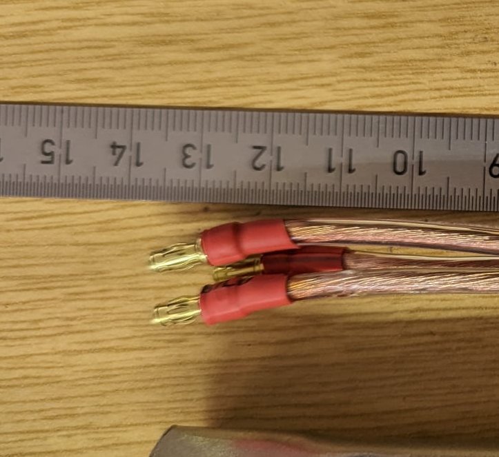
¶ Power Cables
These cables can be produced in a single step to accelerate the over all build time. The following cables will be produced in this manual:
- Weipu
- Charging Port
- Switch and Sense Battery Input + ESC out
- ESC Input + ESC out
- Motor Cables Output
¶ Weipu Connector
¶ Parts Required
- Weipu Connector (SP2112/P2)
- 5 cm Red silicone wire (2.5 mm²)
- 5 cm Black silicone wire (2.5 mm²)
- 2 x female 3.5 mm gold plug (Muldental 81314)
- 4 x shriniking tube (eg. 8mm before shrinking, 2mm after shrinking)
¶ Tool Required
- soldering iron
- solder
- wire stripper (Abisolierzange)
- heat gun to shrink tubes
- helping hand, or tool to hold hot goldplugs and wires
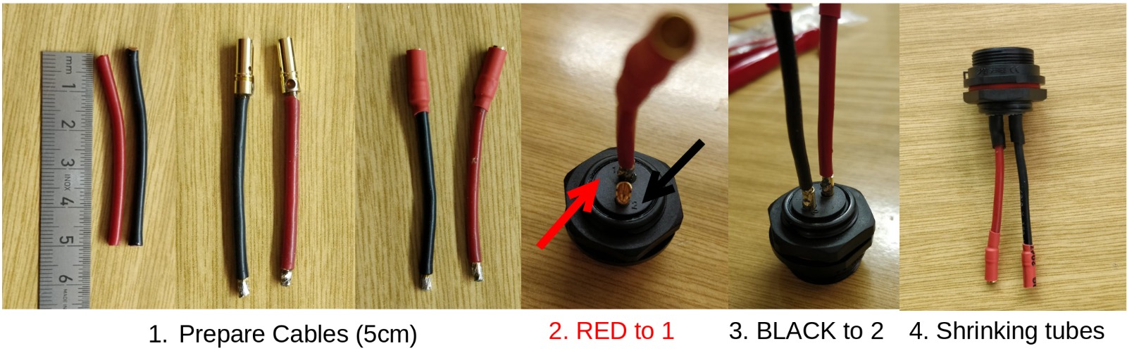
¶ Prepare Weipu Connector
- Cut a black and red cable to 5 cm length
- add solder to both wire ends
- add pigtails to both cables
- solder the red wire to
1 - solder the black wire to
2 - add shrinking tube
¶ Charging Port Cable
¶ Parts Required
- Switchcraft charging port (RASPC10S)
- Switch and Sense PCB
3025 cm Red silicone wire (0.8 - 1.3 mm² / 16 - 18 AWG)3025 cm Black silicone wire (0.8 - 1.3 mm² / 16 - 18 AWG)- 2 x shriniking tube
¶ Tools Required
- soldering iron
- solder
- wire stripper (Abisolierzange)
- heat gun to shrink tubes
- helping hand, or tool to hold hot wires or charging port
¶ Prepare Charging Port
- remove about 4 mm of isolation from both wires
- add solder to both wire ends
- solder wires to connector, like shown in the following image:
.png)
- add shrinking tube
- add isolation tape around the metal contacts
- twist the wires and fix the twisted wires like this:

¶ Switch and Sense Power Cables
¶ Parts Required
- 2 x power cable 55mm, 2.5mm²,
red+black - 2 x power cable 90mm, 2.5mm²,
red+black - 2 x female gold plugs
- 2 x male gold plugs
- shrinking tubes
¶ Tools Required
- soldering iron
- solder
- wire stripper (Abisolierzange)
- heat gun to shrink tubes
- helping hand, or tool to hold hot wires or charging port
¶ Solder power cables to PCB
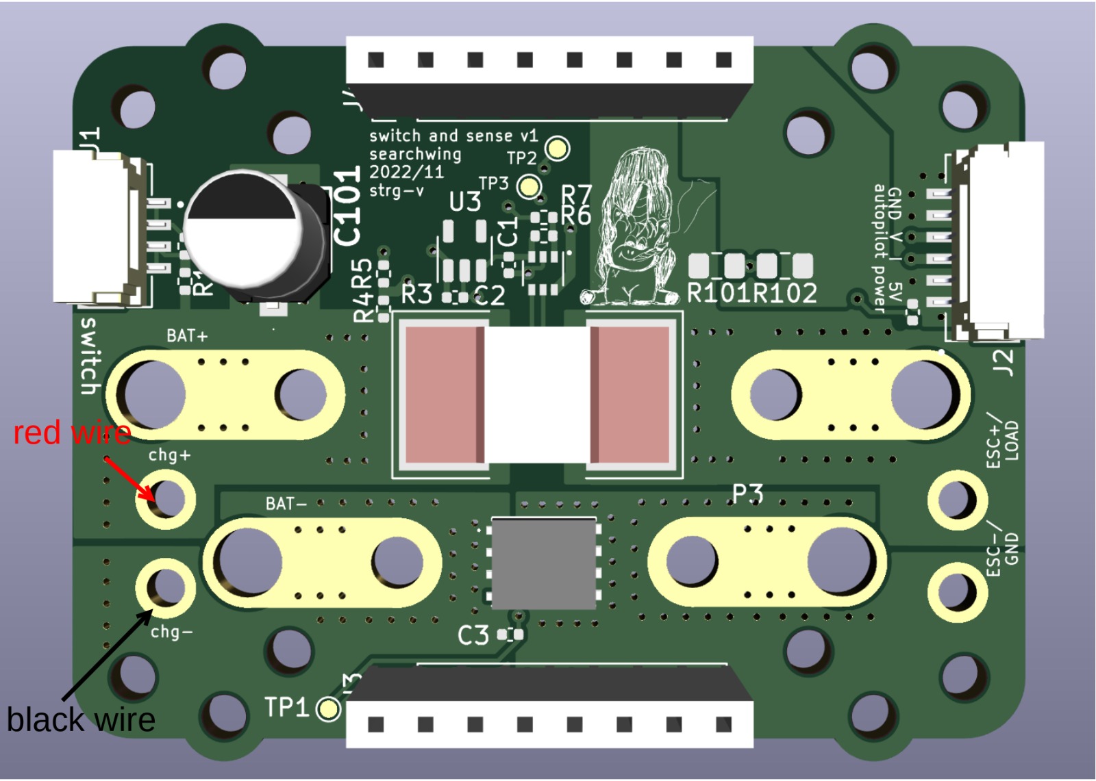
- solder charging port to switch and sense module from the top to the following pads:
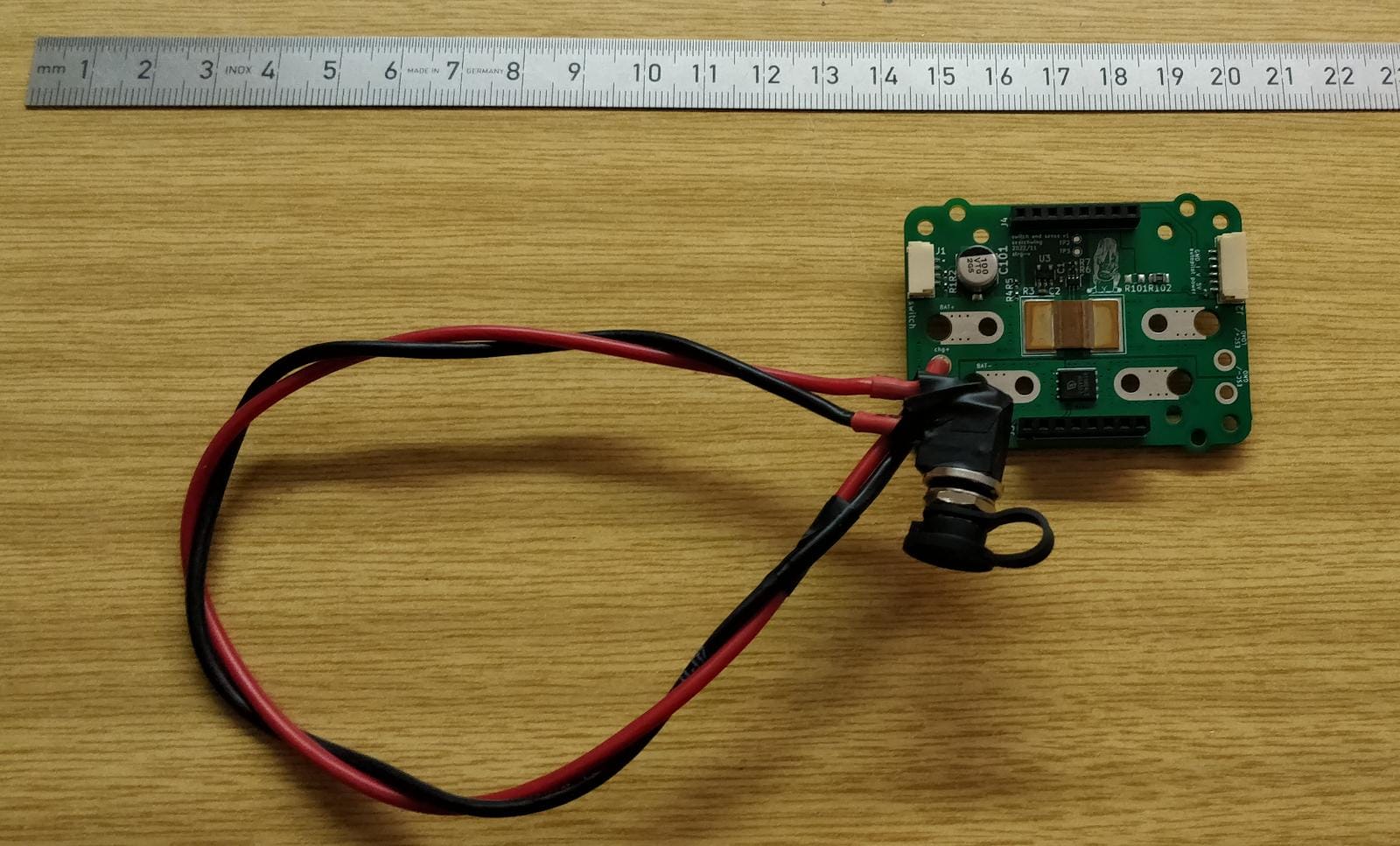
- The assembly should look like this
- Prepare the Battery and ESC power cables like displayed in the following picture:
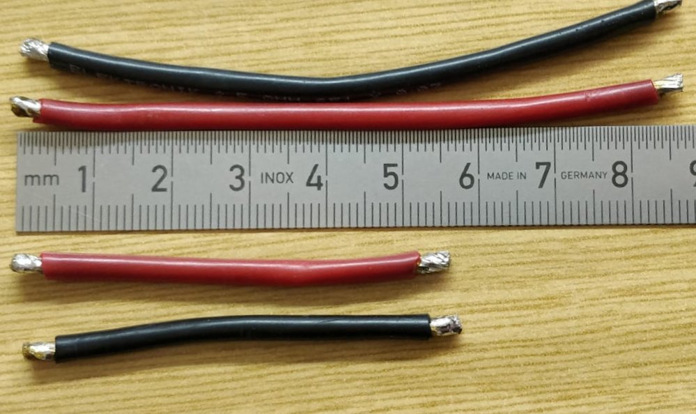
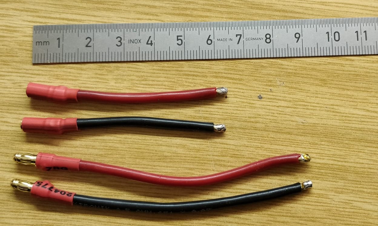
- Solder the gold plugs to the power cables:
- Solder the battery and ESC cables to the PCB like shown in the following picture:
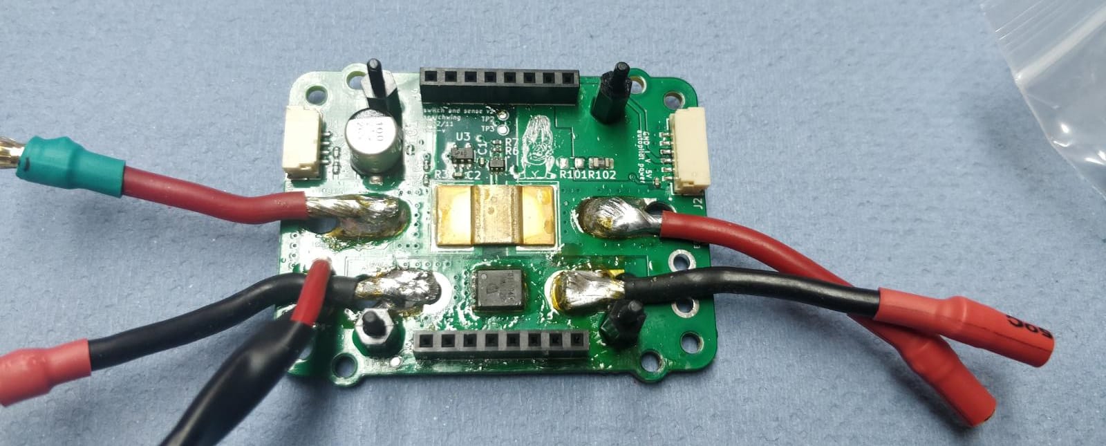
¶ Prepare Motor Outdoor Wires
¶ Parts Required
- 3 x 375 mm, 1.5mm² PVC power cable
- 3 x male gold plug
- 3 x female gold plug
- 1 x 3-wire inlay
- shrinking tubes
¶ Tools Required
- soldering iron
- solder
- wire stripper (Abisolierzange)
- heat gun to shrink tubes
- helping hand, or tool to hold hot wires or charging port
¶ Prepare Motor cables
- Cut the cables to 375 mm / 37.5 cm
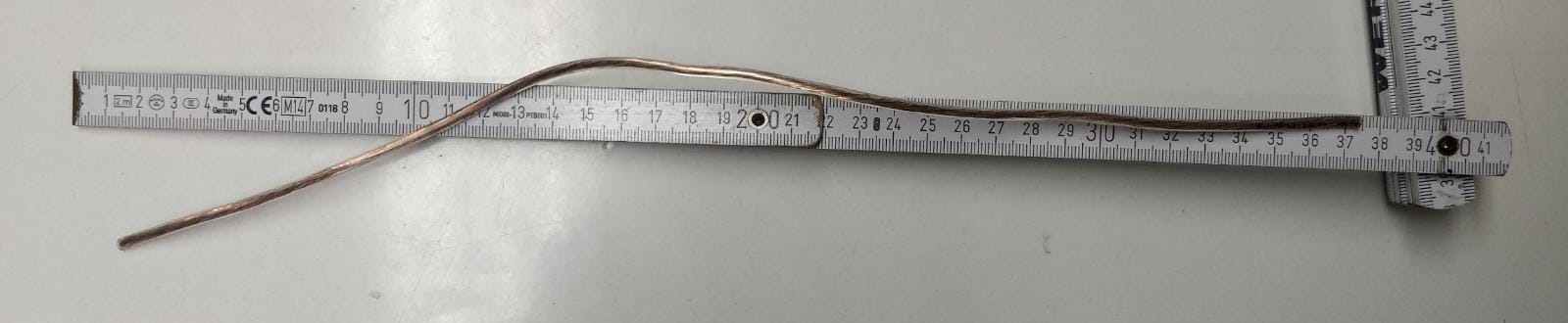
- Push all three wires, wire by wire, thrugh a hole of the 3 wire inlay. Position will be defined later.
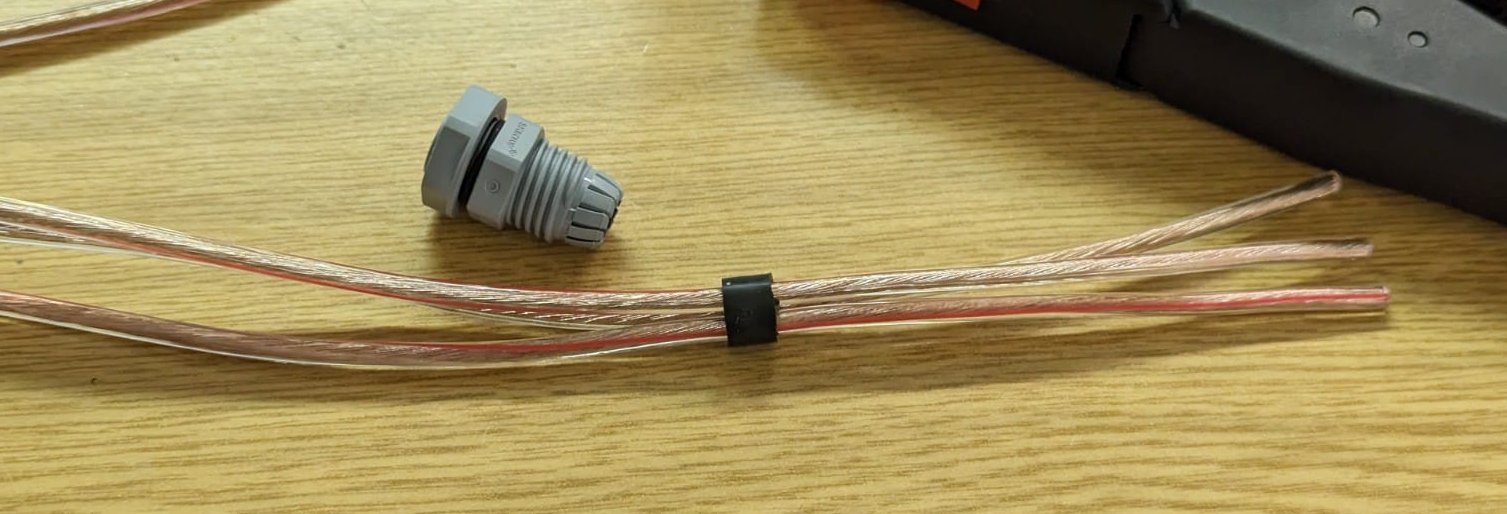
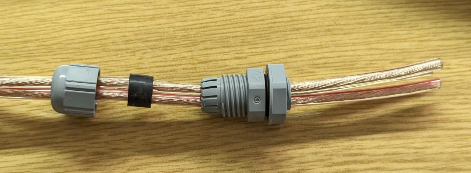
- remove the original rubber seal from the inside of the cable gland
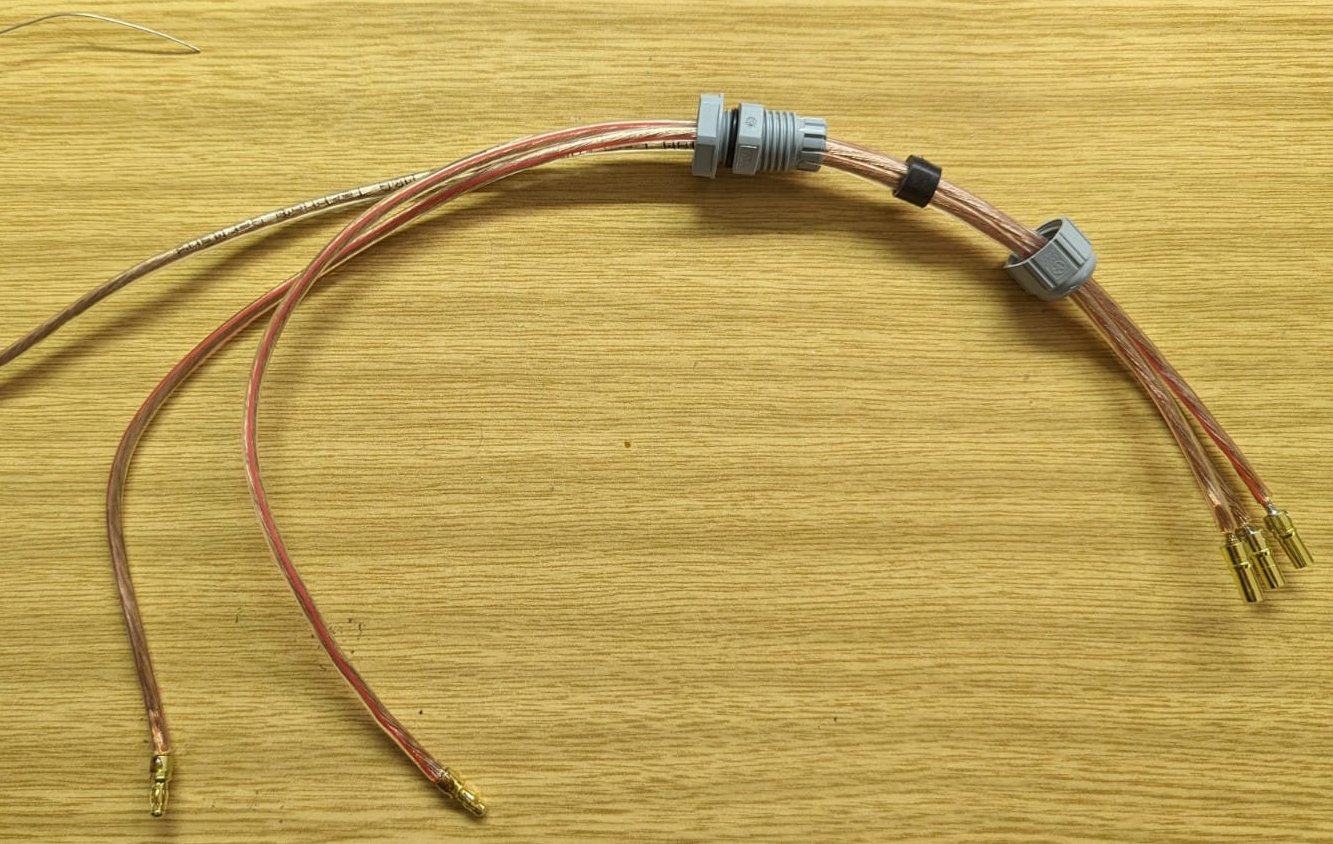
- attach the cable gland as shown in the following picture
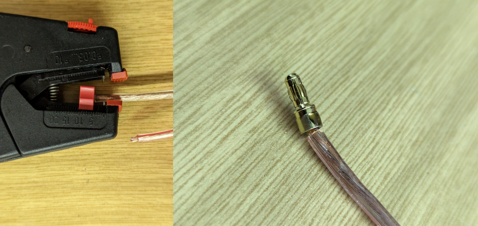
- remove isolation so that it is short enough to fit perfectly into the solder cup
- add solder to each end of the wire
- add female gold plugs
Solder the gold plugs to the correct side.
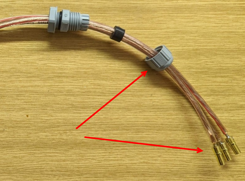
- solder male plugs to the other side, the finished cable should look like this:
- apply shrinking tube to the male plugs, female plugs must be isolated with shrinking tube with glue!