¶ signal-cables
The following cables are required to transfer signals and power between the electrical components inside TheBox:
- switch cable
- Raspberry Pi power+telemetry cable
- remote control cable
- Pixracer power cable
- Telemetry Cable
¶ Switch Cable
¶ Parts Required
- Switch
- 2 x 30 cm pre-crimped JST-GH cable (AGHGH28K305)
- 1 x 4-Pin JST-GH Connector (GHR-04V-S)
- 2 x shrinking tube
¶ Tool Required
- soldering iron
- solder
- wire stripper (Abisolierzange)
- heat gun to shrink tubes
- helping hand, or tool to hold wires etc.
¶ Prepare Switch
- cut off one crimping contact on each pre-crimped JST-GH wire
- remove about 4 mm of isolation on the open wire end
- add solder to the open wire end
- add solder to the two switch contacts
- solder the wires to the switch, there is no ploarity to consider
- add shrinking tube at the solder joints, these tubes should be as short as possible
- twist the wires
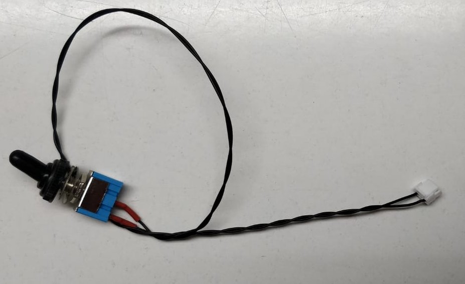
- add the JST-GH 4-pin connector like this:
One contact either in slot 1 or 2, the other contact either in slot 3 or 4
The final assembled cable should look like this:
¶ Raspberry Pi Power + Telemetry Cable
¶ Parts Required
- 6 x 5 cm pre-crimped JST-GH cable (AGHGH28K51)
- 1 x 4-Pin JST-GH Connector (GHR-04V-S)
- 2 x 6 Pin JST-GH Connector (GHR-06V-S)
For v1 from 11/2022:
TODO
¶ Remote Control Cable
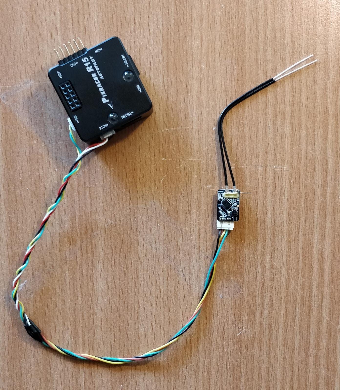
The cable used to attach the remote control transceiver to the Pixracer should be supplied with the transceiver. If not, you need to creaet a cable as follows:
The cable connects receiver in the plane FrSky R-XSR to 2 ports ob the PixRacer: RCIN and FRS.
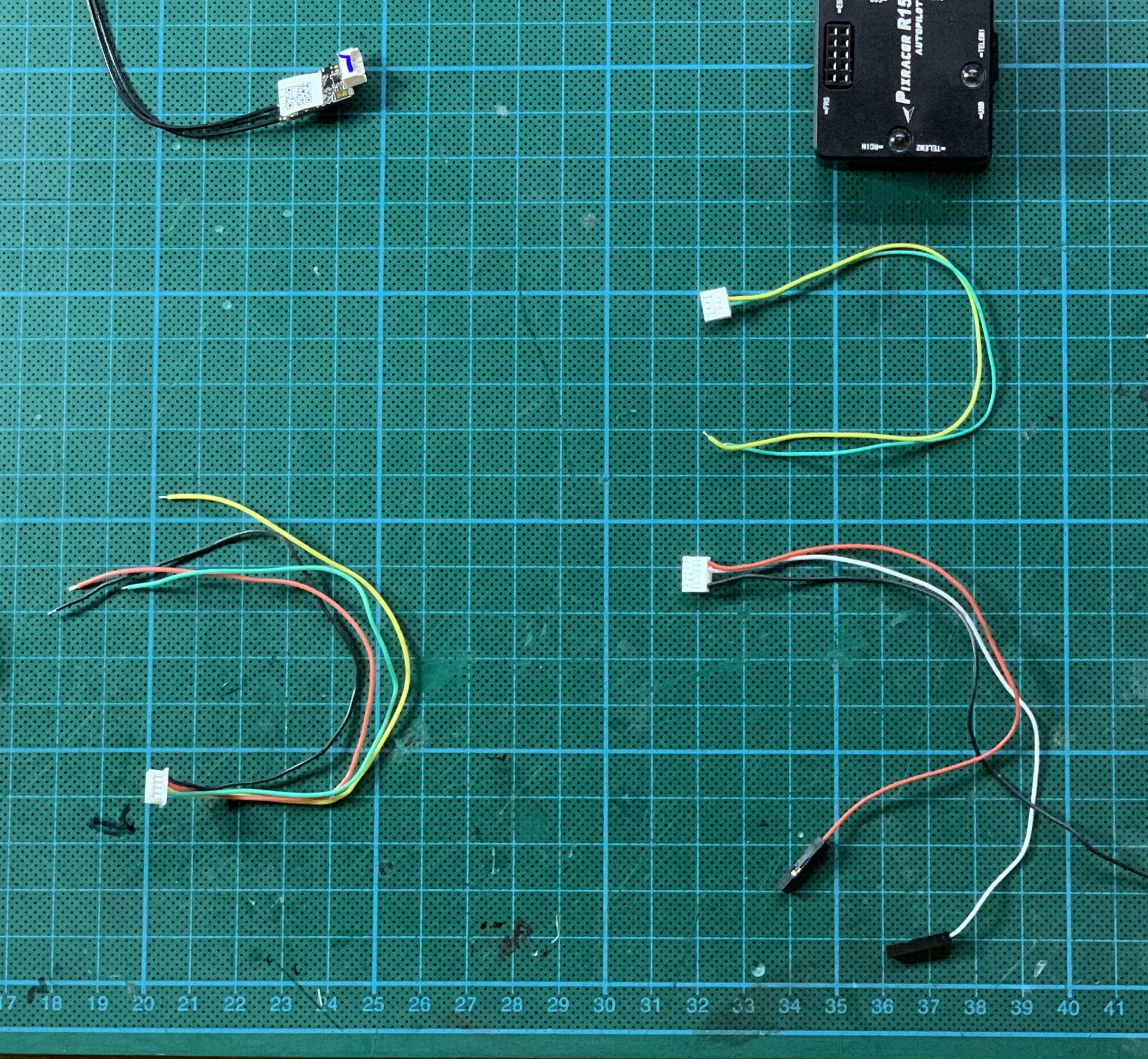
You need:
- From FrSky-Receiver:
- Plug with 5 cables
- Remove the white one
- From PixRacer:
- JST-5 connections (fitting the RCIN connection)
JST-4 connections (fitting the FRS connection)
Cable must be drilled!
¶ Pixracer Power Cable
In version 1 the current sense and voltage sense are swapped on the PCB, therefore the cable needs to have to swapped wires in order to use the sensor data.
For v1 from 11/2022:
TODO
¶ Telemetry Cable
¶ Required Materials
- 8x 15 cm precrimped JST cable - (AGHGH28K305)
- 7x M20 Crimp Contacts - (M20-1160042)
- 1 x JST GH 4 Pin - Power - (GHR-04V-S)
- 1 x JST GH 6 Pin - Serial Port - (GHR-06V-S)
- 1 x 2x8 Pin Connector - Telemetry IDC Connector - (M20-1070800)
¶ Preperations
- Remove from all 8 precrimped JST wire a single contact at the end of each wire.
- Use a crimping tool to attach to 6 wires a M20 crimp-contact. Two cables have to share one crimping contact. The following picture shows how the shared contact should look:
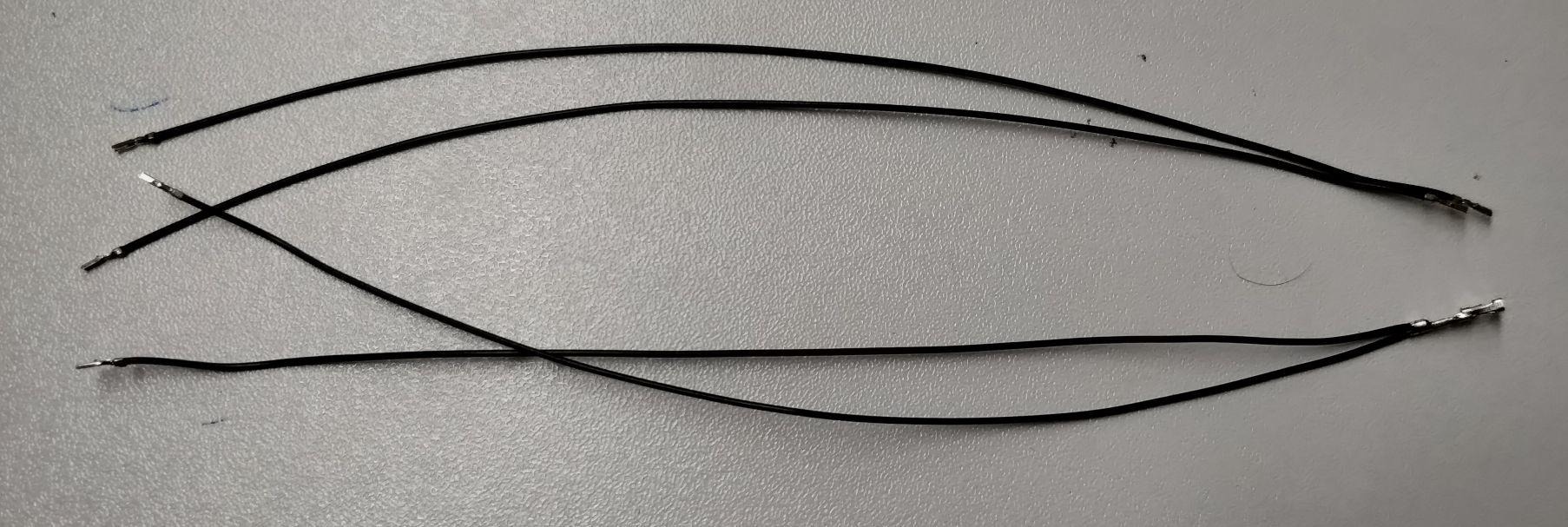
This is done by normaly following the crimping process, but instead of inserting one wire, inserting two wires at the same time.
¶ Overview
The modem is connected to the PixRacer Telem2 port and the power module. The following picture shows an overview of the connections:
The following image shows the wiring diagram of the cable. The 16-Pin connector is viewed from the back!
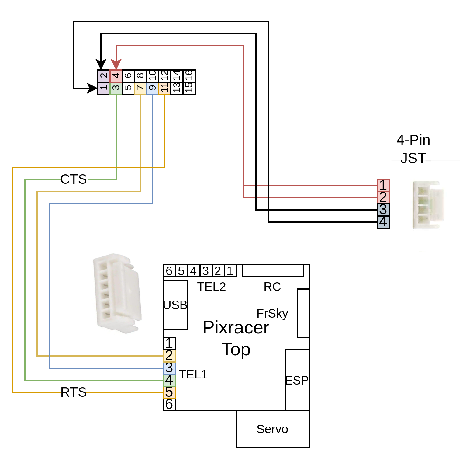
The 4-Pin JST-Connector is used for power connection with the power module, the 6-Pin JST-Connector is used for data transfer between Pixracer and the telemetry. The 16-Pin M20 Connector is viewed from the top side.
¶ RFD868 to Power Module
The overview shows that the two 5 V cables (red) from the 4-Pin JST-Connector end in one port of the M20-Telemetry connector. Since this module is able to transmit data up to 80 km, it is required to ensure a propper power connection.
- Use the two wired crimp contact and insert it into 4th slot of the M20 connector, like illustrated in the overview.
- Connect the GND cables as illsutrated.
- Make sure to twist the power and ground cables around each other in order to ensure better cable routing as well as better EMI performance.
¶ UART cable to PixRacer
Since 2022 we use additional to RX and TX UART connections, RTS and CTS in order to control the data flow.
- Use the remaining four prepared wires and complete the connections like illustrated in the overview.
- Twist the cables around each other in order to ensure better cable routing.
Don't attach the GND cable to the Pixracer! Since the RFD module is connected to GND via. the power module, the GND connection via this data cable (over the Pixracer) would create an EMI amplifying GND loop!
- Further details to the Pixracer pinout are found here.

Keep in mind that the TX pin of the Pixracer is wired to the RX pin of the telemetry module. Vise versa with RX -> TX.
So according to the following table:
| PixRacer JST-GH board | RFD868+ IDC connector |
|---|---|
| RX | TX |
| TX | RX |
| RTS | RTS |
| CTS | CTS |
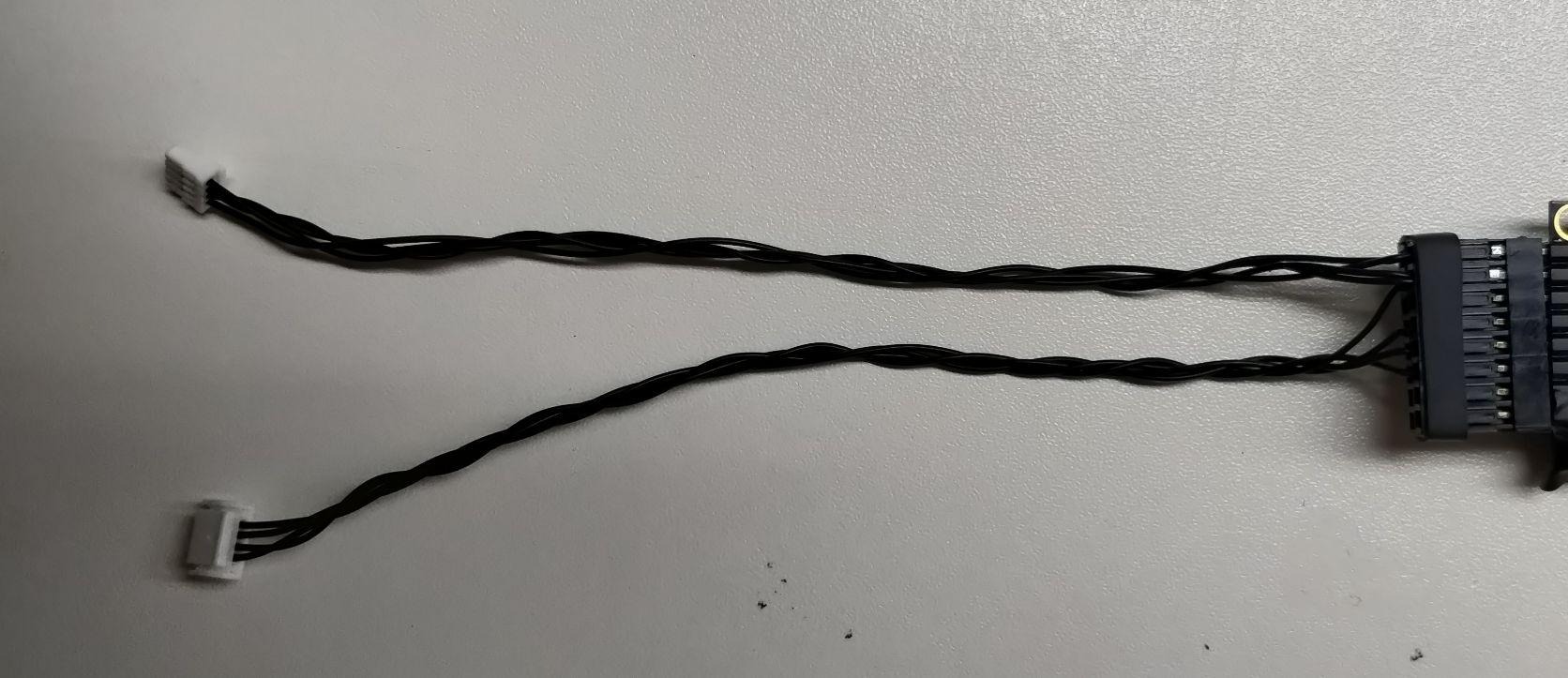
- The final cable should look something like this:
¶ long-range-wifi cables
Only for planes with wifi module
¶ Long-range Wifi Cable
- RP-SMA Buchse BKD - RG174 - stripped/tin - 450mm
- Cut cable to be 20cm
- Remove 9mm of the insulation using a 2.5 terminal size wire stripper
- Solder it to the wifi device
- Use hot glue to stabilize the cable
¶ PoE Ethernetcable for Wifi Module
We can build a 4-wire 100MBit/s ethernetcable for Pi <-> Wifi Module connection and use the spare 4 wires to power the Wifi module using the battery voltage.
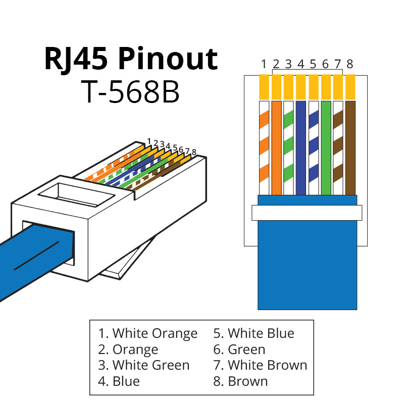
MikroTik uses RJ45 mode B pinout for power distribution, where the PoE is passed trough pins 4,5 (+) and 7,8 (-).
From https://help.mikrotik.com/docs/display/ROS/PoE-Out
¶ Pinout for cable
| Pin | Wifi Side | Pi side |
|---|---|---|
| 1 | As in Image | As in Image |
| 2 | As in Image | As in Image |
| 3 | As in Image | As in Image |
| 4 | As in Image | Connect to 16V+ / Battery+ |
| 5 | As in Image | Connect to 16V+ / Battery+ |
| 6 | As in Image | As in Image |
| 7 | As in Image | Connect to GND / Battery- |
| 8 | As in Image | Connect to GND / Battery- |